11.2. Lubrication of liquid film
Summary
Subject: Large bubble/drop in vertical pipe
Main conclusion: Velocity profile and liquid film thickness in fully-developed film region as function of two-phase viscosity ratio.
Key idea Flow in liquid film is uni-directional, and NS eq can be directly solved to obtain velocity field and liquid film thickness.
References:
Goldsmith and Mason [GM62]
Goldsmith and Mason [GM62] studied the motion of large drops in stagnant liquid confined by a vertical pipe and derived an analytical expression of the terminal velocity in terms of the physical properties of the two fluids, the pipe radius, and the thickness of the liquid film formed between the wall and the liquid-liquid interface. The flow in the developed film is unidirectional, and therefore the inertial term disappears:
where \(p\) is the pressure, \(\rho\) is the density, \(g\) is the magnitude of the gravity acceleration, \(\mu\) is the viscosity, and the subscript \(k\) takes either \(i\) (inside) or \(o\) (outside the drop). The cylindrical coordinates, \(z\) and \(r\), are utilized and the \(z\) axis corresponds to the pipe axis and is directed vertically downward; therefore, the bubble velocity is negative when a bubble moves upward. The drop shape in the front meniscus develops downward, and the thickness of the liquid film, \(h\), far from the front of the drop becomes constant (the film region). In the film region, the drop body is cylindrical, so the interface curvature is given by \(\kappa = 1/(R - h)\), where \(R\) is the radius of the tube. In addition, the normal momentum balance at the interface is given by
where \(\sigma\) is the surface tension. Differentiating this equation with respect to \(z\) yields
since the surface tension term is constant, where \(H\) is constant. The problem to be solved is therefore the following ODE:
By integrating this ODE, we obtain
where \(\alpha\) and \(\beta\) are integration constants. We need to determine the five constants, i.e. \(H\), \(\alpha_{i}\), \(\alpha_{o}\), \(\beta_{i}\) and \(\beta_{o}\). We therefore apply the following conditions (C1-C5) to the general solution:
\(v_{i}\) must be finite at the axis: \(-\infty < v_{i}(0) < \infty\)
\(v_{o}\) is zero (no slip) at the pipe wall (\(r = R\)): \(v_{o}(R) = 0\)
The velocity profiles satisfy the continuity equation:
The velocities are continuous at the interface: \(v_{i}(R-h) = v_{o}(R-h)\)
The tangential viscous stress is continuous at the interface:
where \(u\) is the terminal velocity of drop.
For C1, \(\alpha_{i} = 0\), and C2 gives the relation between \(\alpha_{o}\) and \(\beta_{o}\):
Substituting the expression of \(v_{i}(r)\) into the second equation of Eq. (11.19) (C3) gives
Therefore, the constant \(\beta_{i}\) is given as
Thus, the internal velocity profile is
The external velocity profile is
Using Eq. (11.21) for the constants yields
In order to obtain \(\alpha_{o}\), we consider the continuity of the tangential stress (C5). The velocity gradients are
At \(r = R - h\), the viscous stresses balance, so
Rearranging this yields \(\alpha_{o}\)
where \(\Delta \rho = \rho_{i} - \rho_{o}\). Note that for rising drop \(\rho_{i} < \rho_{o}\), so that \(\Delta \rho < 0\). Thus, the external velocity profile is
C3 for the external velocity field becomes
C4, the continuity of the velocity filed at the interface, can be expressed using Eqs. (11.24) and (11.30):
The pressure gradient \(H\) can be obtained from this equation as
where
and
An example of the calculation procedure is as follows:
For a given \(u\), compute \(h\) from Eq. (11.31).
Update \(h\) by an iterative manner until \(h\) satisfies the continuity equation (11.31).
Draw velocity profiles using Eqs. (11.24) and (11.30). Fig. 11.2 shows an example of the velocity profiles inside and outside a drop (system 11 in the literature).
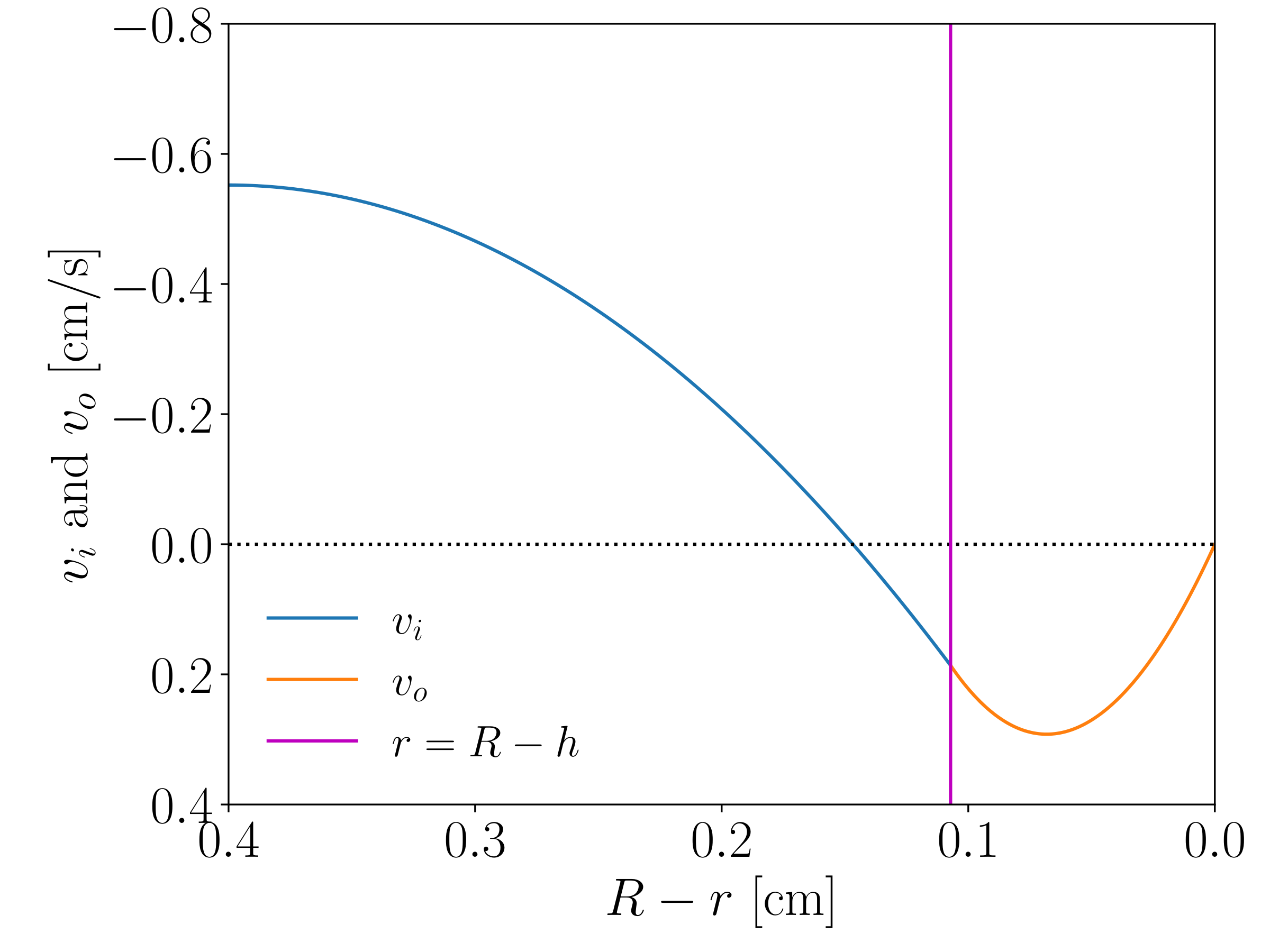
Fig. 11.2 Velocity profile. \(\Delta \rho = -0.214\) g/cm\(^{3}\), \(\mu_{o} = 0.1224\) Pa s, \(\mu_{i}/\mu_{o} = 1.1\), \(R = 4\) mm, \(u = -0.183\) cm/s. The calculated \(h\) is 1.07 mm.
A limiting case of special interest is of gas bubbles. In this case, \(\mu_{i} / \mu_{o} \ll 1\), and therefore we may neglect \(\mu_{i}\) in the derivation. Eq. (11.33) reduces to
Since the internal viscous stress does not play a role, C5 becomes
Hence,
With this coefficient, the continuity equation, C3, gives
The velocity profile is
Fig. 11.3 shows an example of the external velocity profile. The zero-shear stress condition can be seen, that is, the velocity gradient is zero at the bubble surface.
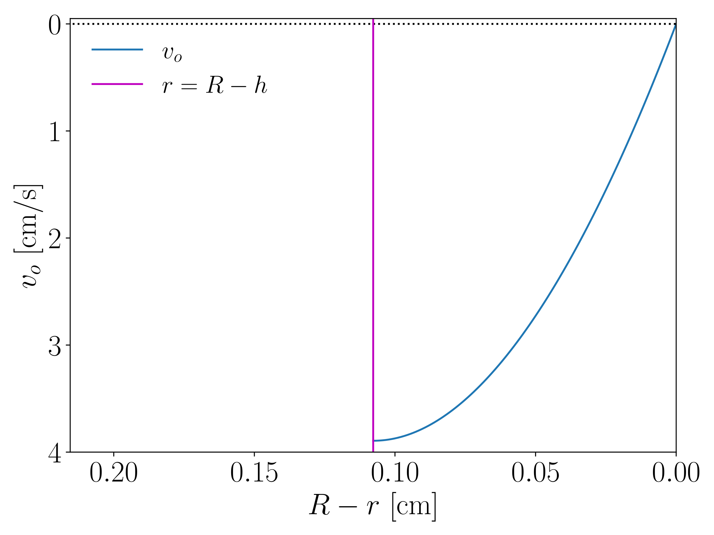
Fig. 11.3 Velocity profile. \(\Delta \rho = -0.985\) g/cm\(^{3}\), \(\mu_{o} = 0.13\) Pa s, \(R = 4\) mm, \(u = -2.15\) cm/s. The calculated \(h\) is 1.08 mm.